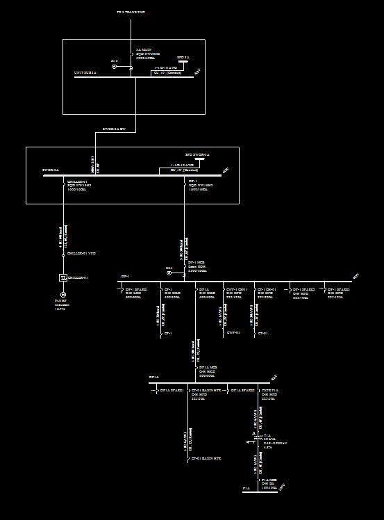
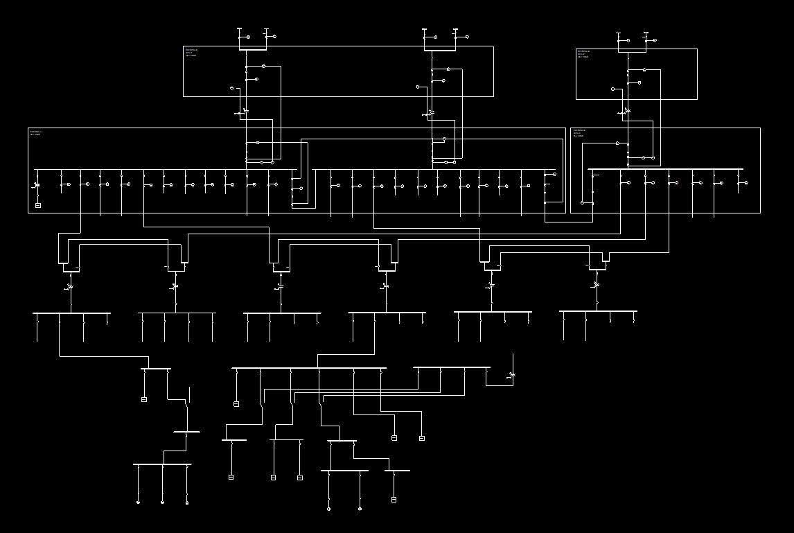
The most critical step of a power systems analysis is to build an accurate single-line diagram (SLD). The SLD is constructed using specific information from all devices and components in the electrical system. We do not utilize inferior methods of performing studies such as infinite bus calculations and using generic device models, nor do we make unfeasible recommendations.
Short circuit analysis determines the fault currents at each bus in the system. These fault currents are used to evaluate the equipment ratings and are also used in the protective device coordination study. The short circuit currents are calculated for three-phase bolted faults, single line to ground faults as well as multiple scenarios, if applicable.
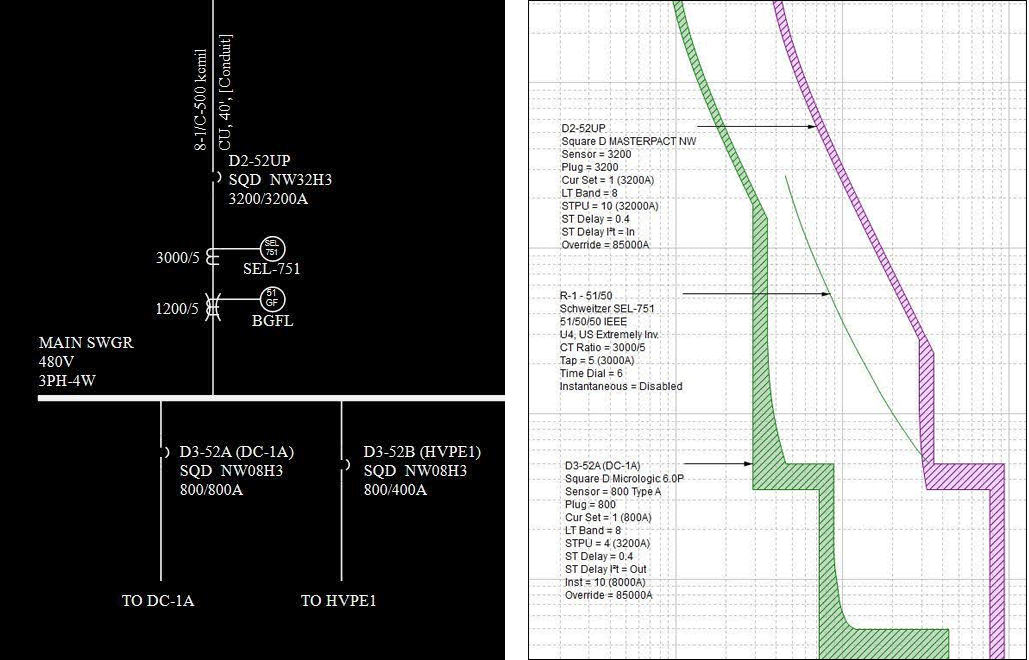
Protective device coordination is an analysis of the time current curves of all overcurrent protective devices (OPDs) in the electrical system. In a properly coordinated system, the OPDs are adjusted in such a way that if a failure occurs, only the smallest possible portion of the electrical system will be affected. Compromise is always required between system protection, arc flash hazard, and continuous electrical service in determining protective device settings.
Time Current Characteristic (TCC) Curves show the time current characteristic curves for all overcurrent protective devices in the system as they are currently installed. TCC curves graphically show the times and order in which each protective device will “trip.” Any areas of miscoordination will be apparent from the overlapping curves of the various devices.
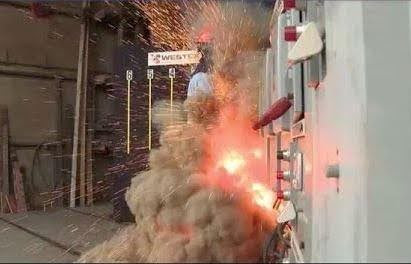
An arc flash can occur for several reasons: lack of maintenance, insulation failure, dropping a tool, human contact with energized equipment, etc… Incident energy of just 1.2 cal/cm2 can cause second degree burns on bare skin (IEEE P1584). As such, it is common for arc flash injuries to cause permanent damage. Simply equipping your maintenance staff with the proper PPE can help to shield them from heat exposure and mitigate some of the more common life-threatening dangers associated with arc flash.
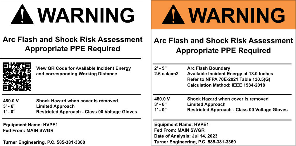
NFPA-70E, Standard for Electrical Safety in the Workplace, requires an arc flash risk assessment to determine the incident energy exposure to personnel and equipment labeling to list the personal protective equipment (PPE) required when working on these energized systems. OSHA references NFPA-70E as a guide for the development of safe work practices around energized electrical equipment.
The arc flash hazard analysis provides the information required for preparing arc flash warning labels as well as the necessary hazard information required prior to any maintenance on or near energized equipment in accordance with the requirements of NFPA-70E. As part of the arc flash hazard analysis, we consider multiple operating conditions as applicable to ensure our reports identify the worst-case arc flash conditions. We provide feasible methods to minimize the arc flash hazard where possible.
Arc flash hazard warning labels will be adhered to all electrical distribution equipment, documenting the arc flash incident energy (AFIE) which specifies the level of Personal Protective Equipment (PPE) required.
Per NFPA-70E, the study shall be reviewed for accuracy at intervals not to exceed 5 years. Where the review of the data identifies a change that renders the label inaccurate, the label shall be updated. Often, the available fault current from the utility has changed since the original study which would require all labels to be replaced. Many of our clients have over one hundred labels and some over one thousand. With that number of labels replacing is very costly. To streamline this, we offer QR code labels. We have our own QR code database which contains the arc flash warning label with the specific information for the equipment. The QR code labels allow the virtual labels to be updated in the database without removing, reprinting, and reapplying the physical label.